Electronics, Circuit Diagrams and Schematics

Thursday, June 01, 2006

High Intensity LED Flashlights and Multi-Color Displays

This flashlight has three different modes of operation, regular flashlight, flashing LEDs, and sound-operated light.

Flashlight in action:


Most small AA battery type flashlights use two cells, but that does not supply quite enough voltage for these LEDs, so parts from two plastic flashlights were joined together to allow room for three AA cells. The LEDs were mounted in the head of the flashlight with epoxy, with the four white ones in the center pointing forward surrounded by the six flashing LEDs pointing outwards. A small slide switch was added to select either white light or flashing colors.

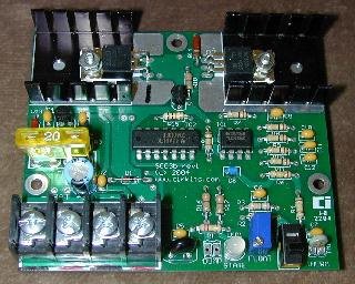
Two double AA battery holders were attached back-to-back for a total of four AA batteries. Three small circuit boards were constructed, one for the switches and controls, one for circuitry, and one for the LEDs themselves. These were the stacked on top of each other and wired together attached to the battery holders. Plastic tape to protect the electronics and a small plastic base was also installed.

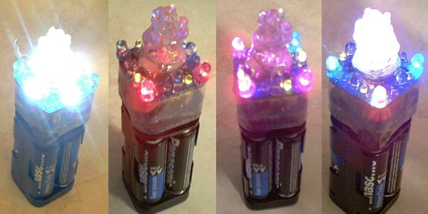
The display uses four white LEDs for regular flashlight use, four RGB flashing LEDs and eight single color LEDs powered by two flashing circuits for the flashing mode, and three regular RGB LEDs and nine single color LEDs for the sound-operated display in the center. The first picture below shows the four white LEDs, the second and third are the flashing LEDs, and the last is the flashing LEDs with all of the sound-operated LEDs on as well.

The sound-operated mode uses a five-step discrete bar graph circuit to drive a multi-LED display. An electret condensor microphone and preamp supplies the audio signal to the display circuit. The pictures below show the level of light getting higher with the audio signal, but what they don't show is how the color of the light changes from dull purple to blue, green, red, orange, and finally yellow and white as the sound gets louder. It is a very nice effect, almost looking like a flame dancing to the music!

For more details plus schematics check the ElectronicPeasant

Friday, May 19, 2006

12 Volt 20 Amp Solar Charge Controller

This circuit regulates the power flowing from a photovoltaic panel into a rechargeable battery.

Device:

It features easy setup with one potentiometer for the float voltage adjustment, an equalize function for periodic overcharging, and automatic temperature compensation for better battery charging over a wide range of temperatures.

The design goals of this circuit were efficiency, simplicity, reliability, and the use of field replaceable parts. A medium power solar system can be built with the SCC3, a 12V solar panel that is rated from 100 milliamps to 20 amps, and a lead acid or other rechargeable battery that is rated from 500 milliamp hours to 400 amp hours of capacity.

It is advisable to match the solar panel's maximum current to the battery's amp-hour rating (C), a typical battery charging current is C/20, so a 100 amp hour battery should have a solar panel rating of around 5 amps. Consult the battery manufacturer's data sheets for the best rating

Specifications:

Maximum solar charging current: 20 Amps
Nominal battery voltage: 12V.
Night time battery current drain: 1.3ma

You can find the full specifications and a diagram at Solorb.com

Saturday, April 22, 2006

PC To TV (VGA to Scart) Signal Converter

The circuit

Here is the circuit for VGA to scart connection. It is basically a circuit which takes VGA signals and converts it to RGB + composite sync signal which can be fed to TV via SCART connector. VGA card picture components RED, GREEN and BLUE are already at the correct voltage level (0.7Vpp) and has correct impedance (75 ohm) for direct connection to correspondign inputs in the TV. What needs to be done is to combine separate horizonal and vertical sync signal from VGA card to one composite sync signal which is feed to TV video in pin in SCART connector. This sync signal conversion is done by the electronics in the circuit. The circuit has also sends correct level signal to the TV RGB input enabling control pin in the SCART connector (pin 16).

VGA to Scart Schematic (click to view):


How the circuit works
This circuit is designed for converting normal VGA signals standard RGB signals and composite sync signal. The circuit is quite simple, because RGB signal ouput from VGA card is already standard 0.7Vpp to 75 ohm load. RGB+composite video format is the signal format needed by the TV input. Besides that format conversion special drivers is needed to set the VGA card to suitable refresh rate for normal TV.


For sync signals there is a circuit which combines horizonal and vertical sync signals to from composite sync singals. The circuit is simply based on one TTL chip with four XOR ports, two resistors and two capacitors. TTL chip was logical choise because VGA sync signals are TTL level signals.


The sync signal combiner has a system to adjust to different sync polarities so that it always makes correct composite sync signals. VGA card uses different sync signal polarities to tell the monitor which resolution is used. This circuit adjusts to sync signal polarity changes in less than 200 milliseconds, which is faster than setting time of a normal VGA monitor in the display mode change.

The circuit needs well regulates +5V (+/-5%) power supply and takes about 120 mA current.

Circuit PCB Layout:

Building the circuits
VGA to TV converter is quite easy to build if you have some experience in building electronic circuits. The electronics of the circuits can be easily built to a small piece of veroboard and no special circuit board is needed. I used this approach in my prototype.
Remember to add powerfeed to the chip U1. It has not been marked to the schematic. U1 has ground at pin 7 and +5V power input at pin 14.


The circuit need well-stabilized power +5V power source (actual voltage can be in 4.75V to 5.25V range). The circuit takes less than 150 mA current, so you don't need a large power supply. If you don't have anythign suitable avalable, you can always use a small general purpose wall transformer and a small +5V voltage regulation circuit. If your computer graphics card is VESA DDC compliant, it might have +5V available at VGA connector pin 9 (the standard have option that VGA card can have +5V at pin 9, but it does not necessarily have to have this). You can test easily if your computer has this +5V output using multimeter.

Final Circuit:


VGA to TV converter component list:

Main circui tU1 74LS86 (74HC86 or 74HCT86 can also be used)
C1 22 microfarads 16V electrolytic capacitor
C2 use 47 uF 16V electrolytic for more reliable operation (22 uF listed schematic can cause problems in some cases)
R1,R2 2.2 kohm, 1/4 W
R3,R4,R5 2.2 kohm, 1/4 W
R6,R7,R9 47 ohm, 1/2 W
R8 120 ohm, 1/2 W
T1,T2 BC547B (2N2222 should also work but note the different pinout)
P1 15 pin SUB-D connector (DE-15)


Output connector: 21 pin EURO/SCART connector

Wiring: Red, Green, Blue and Composite Sync lines should be wired using 75 ohm coaxial cable for best picture quality, but can be replaced with normal shielded wire.


Power supply components:

7805 regulator chip
100 uF electrolytic 25V
10 uF electrolytic 16V
100 nF polyester or ceramic condensator
Wall adapter which outputs 8-18V DC and 150 mA or more current
Connector for connecting wall adaptor to circuit


Warning and disclaimer
If you try this circuit and those drivers and do something wrong, there is danger that you damage your TV, graphics card and monitor. So think what you do and double check everything. And remember that you try this at your own risk: I am not responsible if something harmful happens. The material in the document have been checked and is beleieved to be correct, but there is always possibility of errors. And remeber that there are some differences in different graphics cards and TVs, so it is possible that the circuit might not work in your system for some reason. The system has been tested succesfully with 6 different graphics card in 5 different computers using 6 different TVs/monitors

Source Tkk.fi

Friday, April 21, 2006

VU Meter

Volume Unit Meter with a dynamic range of 60 db

by

An audio volume-unit meter displays peak-related audio amplitudes to aid in accurately setting recording levels or for displaying an amplifier's operating conditions. A simple diode and capacitor network provides a classic volume-unit meter's peak-weighted response, but the circuit typically limits response to about 23 dB of displayable dynamic range, and the meter suffers from errors that its pointer's inertia and mechanical "ballistics" introduce. Contemporary displays eliminate the inertia problem by using arrays of lighted elements to form bar graphs, but any shortcomings in response and accuracy characteristics now shift to the signal-processing domain. You can use DSP techniques and applied mathematics to replicate a meter's functions in firmware, but this approach gets relatively expensive if the device doesn't already include DSP functions to spare.

An inexpensive analog meter's weakness remains its peak-hold element, a capacitor that must charge quickly to accommodate large signals and accurately for small signals—two mutually exclusive goals. In addition, the nonideal characteristics of the diodes for full-wave rectification and peak-hold functions also limit an analog volume-unit meter's dynamic range. Preserving 20 dB of display dynamics and monitoring signal levels that can vary over a 40-dB range, which is typical in consumer electronics, call for a circuit with a dynamic range on the order of 60 dB.

In most instances, traditional circuits fail to simultaneously provide the intended accuracy and slew rate, particularly at low signal levels over a wide dynamic range. The circuit below offers a simple configuration that delivers high accuracy over a dynamic range that exceeds 60 dB and provides the rapid-attack/slow-decay characteristics that a high-quality display requires.

Schematic (click to enlarge):


The heart of the circuit is a Linear Technology LT1011 comparator, IC2, which monitors the difference between the incoming signal's amplitude and the peak-detected output. It also delivers charging current to a 4.7-µF hold capacitor, C6, whenever the state of its charge is too low. Unfortunately, the input-to-output delay inherent in comparators and nonlinear amplifiers determines the minimum output-pulse width. If the hold capacitor charges quickly to track large input bursts, the minimum charge step must greatly exceed the level of small signals and thus limits the dynamic range.

Inductor L1 solves the capacitor-response problem by providing an adaptively variable source of charging current. Adding a 10-mH inductor limits the maximum current rate when the comparator generates narrow pulses, thus reducing the minimum charging amplitude step to a smaller level of 1 mV or less. For wider charging pulses, the current automatically ramps up to higher levels to provide the desired high slewing rate. The minimum charge step is essentially proportional to the signal-step size, ensuring a constant relative accuracy of better than 1 dB over a 60-dB signal range. A signal level of –59 dB corresponds to a 13-mV input, and a meter-scale factor of 0 dB of 2V peak corresponds to the input level necessary for a typical gain-of-20 audio power amplifier to deliver 100W rms into an 8Ω load, or approximately 40V peak output.

The circuit also includes two operational-amplifier stages based on Linear Technology's high-accuracy LT1469 dual op amp. The first stage, IC1A, provides gain of a factor of six in this example, so that a 2V input peak provides a 12V output. The second op-amp stage, IC1B, forms a precision inverting half-wave rectifier. The outputs from IC1A and IC1B and the positive-peak-detected voltage across C6 combine at IC2's input to provide a zero-crossing threshold to the comparator. When its input falls below 0V, IC2's output switches on Q1 and delivers charge to C6 until the voltage across C6 reaches or slightly exceeds the amplified audio voltage. The feedback network comprising R8 and C4 provides an optimal volume-unit-metering discharge.

Source WebEE