Electronics, Circuit Diagrams and Schematics

Saturday, April 22, 2006

PC To TV (VGA to Scart) Signal Converter

The circuit

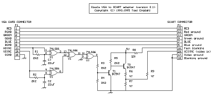
Here is the circuit for VGA to scart connection. It is basically a circuit which takes VGA signals and converts it to RGB + composite sync signal which can be fed to TV via SCART connector. VGA card picture components RED, GREEN and BLUE are already at the correct voltage level (0.7Vpp) and has correct impedance (75 ohm) for direct connection to correspondign inputs in the TV. What needs to be done is to combine separate horizonal and vertical sync signal from VGA card to one composite sync signal which is feed to TV video in pin in SCART connector. This sync signal conversion is done by the electronics in the circuit. The circuit has also sends correct level signal to the TV RGB input enabling control pin in the SCART connector (pin 16).

VGA to Scart Schematic (click to view):


How the circuit works
This circuit is designed for converting normal VGA signals standard RGB signals and composite sync signal. The circuit is quite simple, because RGB signal ouput from VGA card is already standard 0.7Vpp to 75 ohm load. RGB+composite video format is the signal format needed by the TV input. Besides that format conversion special drivers is needed to set the VGA card to suitable refresh rate for normal TV.


For sync signals there is a circuit which combines horizonal and vertical sync signals to from composite sync singals. The circuit is simply based on one TTL chip with four XOR ports, two resistors and two capacitors. TTL chip was logical choise because VGA sync signals are TTL level signals.


The sync signal combiner has a system to adjust to different sync polarities so that it always makes correct composite sync signals. VGA card uses different sync signal polarities to tell the monitor which resolution is used. This circuit adjusts to sync signal polarity changes in less than 200 milliseconds, which is faster than setting time of a normal VGA monitor in the display mode change.

The circuit needs well regulates +5V (+/-5%) power supply and takes about 120 mA current.

Circuit PCB Layout:

Building the circuits
VGA to TV converter is quite easy to build if you have some experience in building electronic circuits. The electronics of the circuits can be easily built to a small piece of veroboard and no special circuit board is needed. I used this approach in my prototype.
Remember to add powerfeed to the chip U1. It has not been marked to the schematic. U1 has ground at pin 7 and +5V power input at pin 14.


The circuit need well-stabilized power +5V power source (actual voltage can be in 4.75V to 5.25V range). The circuit takes less than 150 mA current, so you don't need a large power supply. If you don't have anythign suitable avalable, you can always use a small general purpose wall transformer and a small +5V voltage regulation circuit. If your computer graphics card is VESA DDC compliant, it might have +5V available at VGA connector pin 9 (the standard have option that VGA card can have +5V at pin 9, but it does not necessarily have to have this). You can test easily if your computer has this +5V output using multimeter.

Final Circuit:


VGA to TV converter component list:

Main circui tU1 74LS86 (74HC86 or 74HCT86 can also be used)
C1 22 microfarads 16V electrolytic capacitor
C2 use 47 uF 16V electrolytic for more reliable operation (22 uF listed schematic can cause problems in some cases)
R1,R2 2.2 kohm, 1/4 W
R3,R4,R5 2.2 kohm, 1/4 W
R6,R7,R9 47 ohm, 1/2 W
R8 120 ohm, 1/2 W
T1,T2 BC547B (2N2222 should also work but note the different pinout)
P1 15 pin SUB-D connector (DE-15)


Output connector: 21 pin EURO/SCART connector

Wiring: Red, Green, Blue and Composite Sync lines should be wired using 75 ohm coaxial cable for best picture quality, but can be replaced with normal shielded wire.


Power supply components:

7805 regulator chip
100 uF electrolytic 25V
10 uF electrolytic 16V
100 nF polyester or ceramic condensator
Wall adapter which outputs 8-18V DC and 150 mA or more current
Connector for connecting wall adaptor to circuit


Warning and disclaimer
If you try this circuit and those drivers and do something wrong, there is danger that you damage your TV, graphics card and monitor. So think what you do and double check everything. And remember that you try this at your own risk: I am not responsible if something harmful happens. The material in the document have been checked and is beleieved to be correct, but there is always possibility of errors. And remeber that there are some differences in different graphics cards and TVs, so it is possible that the circuit might not work in your system for some reason. The system has been tested succesfully with 6 different graphics card in 5 different computers using 6 different TVs/monitors

Source Tkk.fi

Friday, April 21, 2006

VU Meter

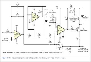
Volume Unit Meter with a dynamic range of 60 db

by

An audio volume-unit meter displays peak-related audio amplitudes to aid in accurately setting recording levels or for displaying an amplifier's operating conditions. A simple diode and capacitor network provides a classic volume-unit meter's peak-weighted response, but the circuit typically limits response to about 23 dB of displayable dynamic range, and the meter suffers from errors that its pointer's inertia and mechanical "ballistics" introduce. Contemporary displays eliminate the inertia problem by using arrays of lighted elements to form bar graphs, but any shortcomings in response and accuracy characteristics now shift to the signal-processing domain. You can use DSP techniques and applied mathematics to replicate a meter's functions in firmware, but this approach gets relatively expensive if the device doesn't already include DSP functions to spare.

An inexpensive analog meter's weakness remains its peak-hold element, a capacitor that must charge quickly to accommodate large signals and accurately for small signals—two mutually exclusive goals. In addition, the nonideal characteristics of the diodes for full-wave rectification and peak-hold functions also limit an analog volume-unit meter's dynamic range. Preserving 20 dB of display dynamics and monitoring signal levels that can vary over a 40-dB range, which is typical in consumer electronics, call for a circuit with a dynamic range on the order of 60 dB.

In most instances, traditional circuits fail to simultaneously provide the intended accuracy and slew rate, particularly at low signal levels over a wide dynamic range. The circuit below offers a simple configuration that delivers high accuracy over a dynamic range that exceeds 60 dB and provides the rapid-attack/slow-decay characteristics that a high-quality display requires.

Schematic (click to enlarge):


The heart of the circuit is a Linear Technology LT1011 comparator, IC2, which monitors the difference between the incoming signal's amplitude and the peak-detected output. It also delivers charging current to a 4.7-µF hold capacitor, C6, whenever the state of its charge is too low. Unfortunately, the input-to-output delay inherent in comparators and nonlinear amplifiers determines the minimum output-pulse width. If the hold capacitor charges quickly to track large input bursts, the minimum charge step must greatly exceed the level of small signals and thus limits the dynamic range.

Inductor L1 solves the capacitor-response problem by providing an adaptively variable source of charging current. Adding a 10-mH inductor limits the maximum current rate when the comparator generates narrow pulses, thus reducing the minimum charging amplitude step to a smaller level of 1 mV or less. For wider charging pulses, the current automatically ramps up to higher levels to provide the desired high slewing rate. The minimum charge step is essentially proportional to the signal-step size, ensuring a constant relative accuracy of better than 1 dB over a 60-dB signal range. A signal level of –59 dB corresponds to a 13-mV input, and a meter-scale factor of 0 dB of 2V peak corresponds to the input level necessary for a typical gain-of-20 audio power amplifier to deliver 100W rms into an 8Ω load, or approximately 40V peak output.

The circuit also includes two operational-amplifier stages based on Linear Technology's high-accuracy LT1469 dual op amp. The first stage, IC1A, provides gain of a factor of six in this example, so that a 2V input peak provides a 12V output. The second op-amp stage, IC1B, forms a precision inverting half-wave rectifier. The outputs from IC1A and IC1B and the positive-peak-detected voltage across C6 combine at IC2's input to provide a zero-crossing threshold to the comparator. When its input falls below 0V, IC2's output switches on Q1 and delivers charge to C6 until the voltage across C6 reaches or slightly exceeds the amplified audio voltage. The feedback network comprising R8 and C4 provides an optimal volume-unit-metering discharge.

Source WebEE

Thursday, April 20, 2006

Rain Detector

This circuit uses a sensor made of a small piece of etched PC board and a simple SCR circuit to detect rain and sound a buzzer. The SCR could also be used to activate a relay, turn on a lamp, or send a signal to a security system.

Schematic:


Parts:
Part Total Qty. Description Substitutions
R1 1 1K 1/4 W Resistor
R2 1 680 Ohm 1/4 W Resistor
D1 1 1N4001 Silicon Diode
BZ1 1 12V Buzzer
S1 1 SPST Switch
SCR1 1 C106B1 SCR 106CY
SENSOR 1 See Notes
MISC 1 Board, Wire, Case,
PC Board (For Sensor)

Notes

1. The sensor is a small piece of PC board etched to the pattern showen in the schematic. The traces should be very close to each other, but never touching. A large spiral pattern would also work.

2. Make sure to use a loud buzzer.

Source Aaroncake.net

Wednesday, April 19, 2006

12 Volt GEL cell charger

Recently, a fellow amateur was looking for a gel cell charger which would first charge at a fixed rate and then later switch to a trickle charge when the cell was fully charged. After reviewing several catalogs and web sites, the MAX712 IC was discovered. This IC meets all the requirements for almost any type of battery charging system. The circuit in Figure 1 was designed specifically for 12 volt gel cells.

When a discharged gel cell is connected, the charger goes into a fast charge mode at a fixed rate of 400 ma. After the chip detects the voltage leveling off or when 4 1/2 hours has elapsed. (which ever happens first.) the fast charge will stop. After the fast charge has ended, the IC goes into a trickle charge rate of about 50 ma. This trickle charge continues until 13.8 volts is reached which will stop all charging current since the cell is now fully charged. If the cell voltage should drop for any reason, either a fast charge or trickle charge (IC will detect what is needed) will start again.

When constructing this circuit, be sure to attach a small heat sink to Q1. Apply a DC (partially filtered) voltage of at least 15.3 volts. The voltage must never go below this level even under load conditions. Many of the DC wall transformers available will work just fine as long as they meet the minimum voltage requirement. The input voltage can be as high as 24 volts. If the input voltage must be in the 30 volt range, increase R1 to about 820 ohms.

The output voltage must be aligned prior to use. Disconnect the battery from the circuit and apply power. Connect a digital volt meter or other accurate volt meter to pin 2 (positive lead) and to pin 12 (negative lead). Adjust R7 until exactly 13.8 volts is read.

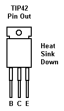
TIP42 PNP Transistor Layout:


Because this circuit will not overcharge a gel cell, the battery can be connected indefinitely. This circuit is designed primarily as a 12 backup system and can be connected to the load provided the device to be powered only draws current during power line interruptions. Use a diode from the battery to load if needed. This circuit makes an excellent battery backup to an amateur transceiver.

The MAX712 IC and the .62 ohm resistor are available from Digi-Key, 701 Brooks Ave, Thief River Falls, MN 56701 (1-800-344-4539). Order part numbers MAX712CPE-ND and 0.62W-1-ND respectively. All other parts are available at Radio Shack.

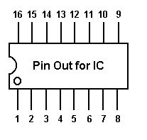
MAX712 IC Controller Layout:

DE N1HFX

PARTS LIST
C1 MAX712 Battery Fast-Charge Controller IC (Cost is $6.27 from Digi-Key)
R1 680 ohm 1/2 watt resistor (Blue Gray Brown)
R2 150 ohm resistor (Brown Green Brown)
R3 68K resistor (Blue Gray Orange)
R4 22K resistor (Red Red Orange)
R5 .62 ohm 1 watt resistor (Blue Red Silver) (Cost is 27 cents from Digi-Key)
R6 1.8K resistor (Brown Gray Red)
R7 10K PCB trimmer resistor (103)
R8 470 ohm resistor (Yellow Violet Brown)
C1 1 microfarad tantalum capacitor (observe polarity)
C2,C4 .01 microfarad capacitor (103)
C3,C5 10 microfarad electrolytic capacitor (observe polarity)
Q1 TIP42 PNP transistor or similar (attach heat sink)
D1 1N4001 Diode (observe polarity)
LED1,LED2 2 volt standard LED (observe polarity)


Schematic layout of the charger:


Source Rason.org

22 Watt Audio Amplifier

The 22 watt amp is easy to build, and very inexpensive. The circuit can be used as a booster in a car audio system, an amp for satellite speakers in a surround sound or home theater system, or as an amp for computer speakers. The circuit is quite compact and uses only about 60 watts. The circuit is not mine, it came from Popular Electronics.

Schematic:


Parts:

Part Total Qty. Description

R1 1 39K 1/4 Watt Resistor
C1,C2 2 10uf 25V Electrolytic Capacitor
C3 1 100uf 25V Electrolytic Capacitor
C4 1 47uf 25V Electrolytic Capacitor
C5 1 0.1uf 25V Ceramic Capacitor
C6 1 2200uf 25V Electrolytic Capacitor
U1 1 TDA1554 Two Channel Audio Amp Chip
MISC 1 Heatsink For U1, Binding Posts (For Output),
RCA Jacks (For Input), Wire, Board


Notes

1. The circuit works best with 4 ohm speakers, but 8 ohm units will do.

2. The circuit dissipates roughly 28 watts of heat, so a good heatsink is necessary. The chip should run cool enough to touch with the proper heatsink installed.

3. The circuit operates at 12 Volts at about 5 Amps at full volume. Lower volumes use less current, and therefore produce less heat.

4. Printed circuit board is preferred, but universal solder or perf board will do. Keep lead length short.

Source Aaroncake.net

Parking-Aid

3 LEDs signal bumper-barrier distance, Infra-red operation, indoor use.

Schematic (click to enlarge):


Parts:


R1_____________10K 1/4W Resistor
R2,R5,R6,R9_____1K 1/4W Resistors
R3_____________33R 1/4W Resistor
R4,R11__________1M 1/4W Resistors
R7______________4K7 1/4W Resistor
R8______________1K5 1/4W Resistor
R10,R12-R14_____1K 1/4W Resistors


C1,C4___________1µF 63V Electrolytic or Polyester Capacitors
C2_____________47pF 63V Ceramic Capacitor
C3,C5_________100µF 25V Electrolytic Capacitors

D1_____________Infra-red LED
D2_____________Infra-red Photo Diode (see Notes)
D3,D4________1N4148 75V 150mA Diodes
D5-7___________LEDs (Any color and size)

IC1_____________555 Timer IC
IC2___________LM324 Low Power Quad Op-amp
IC3____________7812 12V 1A Positive voltage regulator IC


Device purpose:

This circuit was designed as an aid in parking the car near the garage wall when backing up. LED D7 illuminates when bumper-wall distance is about 20 cm., D7+D6 illuminate at about 10 cm. and D7+D6+D5 at about 6 cm. In this manner you are alerted when approaching too close to the wall.
All distances mentioned before can vary, depending on infra-red transmitting and receiving LEDs used and are mostly affected by the color of the reflecting surface. Black surfaces lower greatly the device sensitivity.
Obviously, you can use this circuit in other applications like liquids level detection, proximity devices etc.

Circuit operation:

IC1 forms an oscillator driving the infra-red LED by means of 0.8mSec. pulses at 120Hz frequency and about 300mA peak current. D1 & D2 are placed facing the car on the same line, a couple of centimeters apart, on a short breadboard strip fastened to the wall. D2 picks-up the infra-red beam generated by D1 and reflected by the surface placed in front of it. The signal is amplified by IC2A and peak detected by D4 & C4. Diode D3, with R5 & R6, compensates for the forward diode drop of D4. A DC voltage proportional to the distance of the reflecting object and D1 & D2 feeds the inverting inputs of three voltage comparators. These comparators switch on and off the LEDs, referring to voltages at their non-inverting inputs set by the voltage divider resistor chain R7-R10.

Notes:

* Power supply must be regulated (hence the use of IC3) for precise reference voltages. The circuit can be fed by a commercial wall plug-in power supply, having a DC output voltage in the range 12-24V.
* Current drawing: LEDs off 40mA; all LEDs on 60mA @ 12V DC supply.
* The infra-red Photo Diode D2, should be of the type incorporating an optical sunlight filter: these components appear in black plastic cases. Some of them resemble TO92 transistors: in this case, please note that the sensitive surface is the curved, not the flat one.
* Avoid sun or artificial light hitting directly D1 & D2.
* If your car has black bumpers, you can line-up the infra-red diodes with the (mostly white) license or number plate.
* It is wiser to place all the circuitry near the infra-red LEDs in a small box. The 3 signaling LEDs can be placed far from the main box at an height making them well visible by the car driver.
* The best setup is obtained bringing D2 nearer to D1 (without a reflecting object) until D5 illuminates; then moving it a bit until D5 is clearly off. Usually D1-D2 optimum distance lies in the range 1.5-3 cm.
* If you are needing a simpler circuit of this kind driving a LED or a relay, click Infra-red Level Detector

Source RedCircuits

About...

This is going to be a blog about free schematics, diagrams and various circuits that we find on the Internet. You are welcome to send your own schematics and also comment on the existing ones. Remember to always be careful when you try to build the circuits, and take all neccessary precautions when working with electric currents and voltages.

If you like a circuit, build it at your own risk, and ALWAYS (we will not stop saying this) take precautions and consider all circuits as live ones, that means as operating under high electric currents and voltages!

As for legal stuff, let us remind you that we take no responsibility about any harm that you might cause to yourself or others by using the information found on this site, and we provide the info on this site AS IS and without any warranty...Also note that some of the circuits might be illegal to build or operate in some countries, please check your local regulatory bodies if concerned. Other circuits are dangerous to construct and should not be attempted by the inexperienced.

Finally, all schematics on this site are considered as free. In case a schematic is not free or should not be in here, please contact us and we will remove it ASAP.

That said.. happy browsing!